


The GTS Thermal oil heating systems are constructed and assembled according to the following Regulations and Standards.
- DIN 4754 "Heat transfer systems with other liquid heat transfer fluids than water" and "Safety requirements"
- VDI 3033 "construction, operation and maintenance of heat transfer plants with organic and inorganic heat carriers"
- AD-2000 leaflets
- EC Pressure Equipment Directive 97/23 / EC
- SVTI, GOST, ASME, etc.
The following list may not be complete Because of the diverse applications.
If needed, please contact us so that we can offer you comprehensive advice.

Building Materials Industry
Drying chambers, formwork heating systems
Bitumen, grease and oil industry
Storage tanks, stirrers, heat tracing
Chemical and pharmaceutical industries
Autoclaves, reaction vessels, stirrers,
dryers
Wood, cardboard and paper industry
Presses, dryers, calenders, autoclaves
Food industry
Ovens, deep-frying, boiling pans, distillings
Surface finishing, galvanic
Galvanization baths, pickling baths, painting plants
Textile industry, laundries
Coating, dryers, calenders, washing machines,
washing tunnels
Packaging Industry
Printing machines, dryers
Water or steam are commonly used in heating systems as heat transfer medium.
But at high temperatures require correspondingly high working pressures.
A mineral thermal oil can be used at atmospheric pressure up to 300 ° C.
For comparison water or steam requires a pressure of 85 bar to obtain the same temperature.
With the use of thermo oil there will be no corrosion and sediments in the pipes and fittings of your system.
No expensive and complex water treatment necessary. No risk of freezing at low temperatures, therefore very suitable for combined heating-cooling systems.
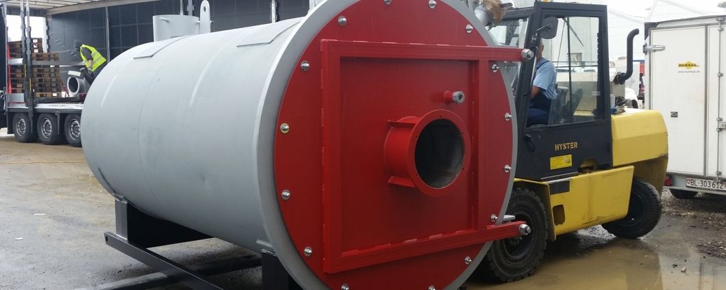
GTS Thermo oil heating systems are generally build as closed systems. The Thermo oil in the expansion tank is blocked from the atmosphere by a Inert gas (Nitrogen). This increases the lifetime of the thermo oil extremely.
The advantages of a GTS Thermo oil plant summarized:
- High temperatures, up to 300 ° C, at atmospheric pressure
- No corrosion
- No risk of damage by freezing
- Low maintenance costs
- High efficiency
- Low investment costs
- No water treatment necessary
- Extremely long service life of the thermal oil
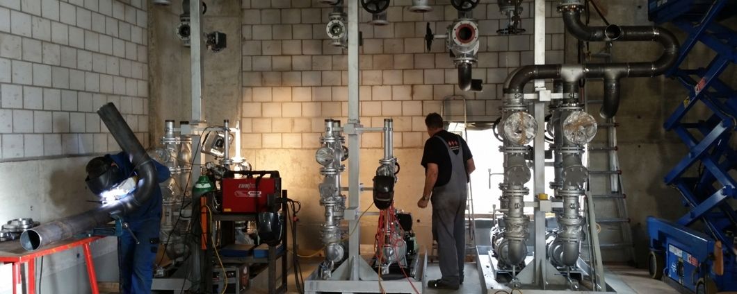
Schematic diagram of a typical GTS thermal oil plant with all the necessary ingredients.
Here with double pump system.
This heating system is also available as compact heating plant or container heating plant in turnkey execution.

| 1 Heater Gas / Oil | 13 Rupture disk | 25 Level controller |
| 2 Burner | 14 Shut-off valve | 26 Level indicator |
| 3 Chimney | 15 Filter strainer | 27 Pressostat |
| 4 Consumer | 16 Check valve | 28 Manometer gauge |
| 5 Expansion vessel | 17 Vibration absorber | 29 Vacuum breaker |
| 6 Circulation pump | 18 Manometer gauge | 30 Safety valve |
| 7 Nitrogen system | 19 Thermostat | 31 Check valve |
| 8 Gas collector | 20 Temperature indicator | 32 Valve |
| 9 Autom. air separator | 21 Thermostat STB | 33 Hose |
| 10 Valve | 22 Flow control | 34 Reduction valve |
| 11 Fill and Drain system | 23 Thermostat STB | 35 Nitrogen |
| 12 Savety valve | 24 Temperature regulation |
GTS Engineering
Stephan Güdel
Binningerstrasse 110
4123 Allschwil
Switzerland
Phone: +41 61 483 10 23
Mail: This email address is being protected from spambots. You need JavaScript enabled to view it.
Page 6 of 7

